Page Contents
Page 1/2
If you’ve been on my homepage, you might have seen the animation below the main header, encouraging you to scroll down. You can even click on it and the website scrolls down for you. Creating that icon took me around 20 minutes and I thought to myself: This could be a great start for someone new to Fusion. Especially because everything I did is possible inside the free version of Fusion inside DaVinci Resolve (Or the free Fusion 9 Standalone). I will try to add as many tips and tricks along the way, to speed up your next Motion Graphics project inside Fusion. Let’s get started!
Set up the Project
Create your Project. I chose 40 frames per second for a buttery smooth animation. For the resolution I kept FHD, but rendered in 800*800. It’s easier if you choose 800*800 directly, you’ll see why later. The resolution doesn’t matter that much, since Fusion is somewhat resolution independent and we’re using a path, more about that later.
First, we will need an arrow. For the animation on the website, I used a path created in Affinity Designer for iPad. I exported it as an SVG which you can import into Fusion as a Path. Remember to use the actual Import dialogue in Fusion, simply dragging and dropping won’t work.
Creating the Arrow in Fusion
But I promised you, that you can do this for free, and maybe you don’t have Affinity Designer, Photoshop, Illustrator or any other tool that could export a SVG Path. So let’s create an Arrow inside Fusion.
Create a new Polygon-Node. Fusion probably created this Polyline canvas in FHD, but we want a rectangle. In the inspector, go to the Image Tab and change the Output Size to Custom. Choose a resolution. For this type of animation a perfect rectangle will be best. I chose 800*800. Fusion will always create the canvas in the project settings resolution. Meaning all Splines and Background nodes use that resolution.
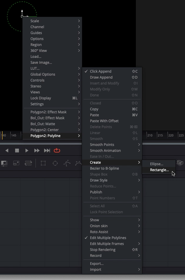
Then right click on the transform handles in the center.
Choose Polygon: Polyline > Create > Rectangle.
Increase the standard size slightly, but keep the sides the same length. Now, you might be wondering what these numbers are, if you come from, for example, After Effects. Where are the absolute pixels?! This is where I get back to resolution independent: Most nodes in Fusion use a relative coordinate system.
This means that X=0 and Y =0 is always the left bottom corner. X=0.5 and Y=0.5 is always the exact center. This is very handy when you want to create something symmetrical.
Now that we have our rectangle, go into the Polygon Nodes first Tab inside the Inspector and rotate it by 45 degrees on the Z-Rotation.
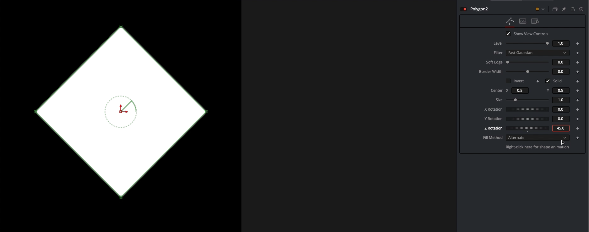
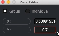
Select the bottom point and press E on your keyboard. The Point Editor opens. Here you can specify the relative position for one or many points at the same time. Increase the Y-Position of the Point. It jumps up and our rectangle is starting to look like the arrow. When we created the rectangle, our mouse position wasn’t exactly in the center, so we also have to change the X-Position to exactly 0.5.
But this is far from intuitive. You can also move the points by hand, and when you’re satisfied you can go into the Point Editor again to align them and make them symmetrical. Remember, if your left outer point is on the location X=0.1 and Y=0.35, then your right outer point should be on X=0.9 and Y=0.35. Once you’re used to a relative coordinate system, you will prefer it over pixel counting.
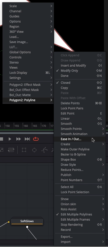
I like to have the edges slightly rounded. Select the upper point and press Shift-S. Well, that is not what we want. Right Click and choose
Polygone: Polyline > Ease In / Out…
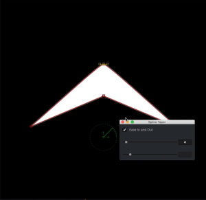
Click on the checkbox and reduce the amount until you’re happy.
Do the same for the other points.
Arrow File
Did something not work and you can’t figure it out? Don’t worry, open the following widget and copy and paste that code into Fusion:
Now we have the same arrow to work with.
On the next page we will create the animation and the final gif.

